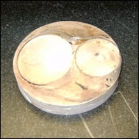
Combustion Chamber Mold Making Instructions
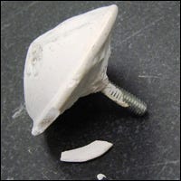
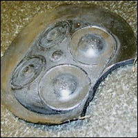
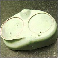
JE recommends using a rigid mold compound such as Auto Body Dent Filler or equivalent. Do not use flexible or brittle materials such as latex, modeling clay, or plaster because they cannot be scribed or measured accurately.
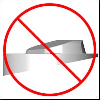
The following molds are examples of chamber molds not accepted by JE.

Procedure 1:
The combustion chamber and valves must be clean and free of carbon deposits. Casting flash or tooling marks should be removed or reasonably smoothed.
Apply a release agent, such as WD-40, to the chamber and bore surfaces before pouring the mold compound.
Install the dowel pins in the block and then install the valves and spark plug in the cylinder head. A rubber electrode cover on the spark plug will help the mold separate easier. This cover can be made from tool dip, which can be purchased at hardware stores such as Home Depot. See picture below.

With the block fastened to an engine stand, bolt the head to the block and rotate it until the deck of the block is level with the floor and upside down. The bottom of the mold must be flat and parallel to the deck, so it is essential that the deck is level and horizontal.

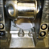
Pour the mold compound through the crankcase. The more “liquid” or “fluid” the molding compound, the better it will conform and allow bubbles to rise away from the chamber. Thicker compounds may need some pressure to ensure it conforms completely (an old piston works well for this). Allow the molding compound to extend into the bore ½” – 2″

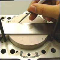
Once the compound has cured, rotate the assembly right side up and remove the cylinder head. Using the dowel pins and a straight edge, scribe a line across the base of the mold. This scribed line must be parallel to the pin axis as shown in picture below.
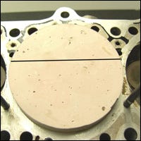
Note: Centerline doesn’t have to be on center of the chamber mold, but it is critical that it is parallel to the wrist pin axis.
Once the line is scribed, remove the mold from the chamber.
Procedure 2:
The combustion chamber and valves must be clean and free of carbon deposits. Casting flash or tooling marks should be removed or reasonably smoothed.
Apply a release agent, such as WD-40, to the chamber and bore surfaces before pouring the mold compound. (Do not apply release agent to the piston).
Drill three or four holes (1/8″ – 3/8″ dia) through the top of an old piston and assemble it on a connecting rod (rings and pin locks are not necessary).
Install the piston/rod assembly on the crankshaft with the main bearings in place.
Install the dowel pins in the block, then install the valves and spark plug in the cylinder head. (Use an electrode cover on the spark plug as described in procedure one.) Then pour the molding compound on top of the piston as shown in the picture below.
With the block fastened to an engine stand, bolt the head to the block and rotate it until the deck of the block is level with the floor and upside down. Then rotate the crankshaft, pressing the piston into the mold compound and allowing the compound to squish through the drilled holes.
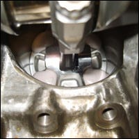
Once the compound has cured, remove the cylinder head from the block, the connecting rod from the crank, and piston/mold from the connecting rod.
Plug reliefs and/or flame slots can either be put in place with clay beforehand or cut out of the finished mold.
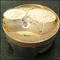
Note: The position of the mold in relation to the bore and wrist pin centerline is critical! Please mark it on the mold with a thin, sharp scribed line. Lines made with Sharpie markers are not accurate enough to be used.
Note: Allow molding compound to completely cure before disassembly!
Note: Do not send press fit piston/rod assemblies as we cannot press them apart at our plant!


